Sunday, May 17, 2015

Philips 40PFL5507H TV firmware restore

Came back home one day to an hourglass on the display of my TV, instead of the usual power up sequence.

IMG_0142

It just sat there for a couple of seconds before going to a blank screen. Reading online I found that it could be due to a corrupted firmware.

From the Philips website I downloaded a copy of the latest firmware and put it on a USB thumb-drive.

TV

However I was unable to get it to start the firmware installation process, regardless of the different methods that the help file included within the firmware download suggested.

I then looked around more and found a copy of the service manual for my TV here.

https://www.scribd.com/doc/178909518/40PFL5507H-12-pdf#download

In it, there was a method to invoke an alternate or backup software/firmware function, to be used in the event the default upgrade application does not start (sounds like me).

1. Disconnect TV from power.

2. Hold the DOWN cursor while reconnecting TV to mains.

3. Backup software application should start.

Following these steps I managed to restore the firmware on my TV (I had to go through channel setup as well, since those were lost)

IMG_0147

IMG_0148

With that done, I proceeded to enjoy some Discovery Channel. Smile

Tuesday, February 24, 2015

Yashica GT Pad of death + Rangefinder cleaning + Light seals

Picked up a Yashica GT for cheap (under USD$15) locally which was known to have the POD (pad of death) issue, basically a small foam piece inside goes crumbly and then the shutter will start going crazy.

IMG_1762

First steps are to disassemble the camera until you can see where the pad is.

IMG_1764

Here I’ve removed the advance lever.

IMG_1765

I planned to do this over the course of a few days, so bagging and labeling the parts was important, putting it all together and then finding out you have some stuff still on the bench is not cool (been there done that).

IMG_1766

ASA dial comes off next.

IMG_1768

Below that is a little washer which is basically what keeps the stationary part of the dial in place.

IMG_1769


IMG_1770

Now we have the film rewind knob

IMG_1771

I wrapped tape around a screwdriver for me to use as a leer against the knob.

IMG_1772


IMG_1773

There’s a small washer right under there.

IMG_1774

Below that there’s yet another washer that I guess keeps light and dust out of the innards.

IMG_1775

After removing 3 screws around the top cover,gently pop it off, there’s a wire still in there for the flash, so be careful.

IMG_1776

I chose to de-solder this wire so I wouldn’t have to be mindful of it while working on the camera.

IMG_1777

Residing within the top cover is the battery test button, I took it out before moving the top cover too much (prevents it from getting lost).

IMG_1778

Here we can see the problem, right there (just above CA in Yashica) is the deteriorated pad.

To get at it, you’d have to separate the lower mechanism from the upper. I did this by temporarily re-installing the advance lever, advancing and then using an allen key depress the lower mechanism.

IMG_1781IMG_1782

With that out of the way now, we can get at the pad, there are other methods that involve disassembling more of the camera so you get better access, however that involves removing part of the leatherette on the front of the camera, I didn’t want to risk damaging that so I chose to do it ‘surgically’.

IMG_1787

Here I’ve straightened out a bobby pin (from SWMBO) and put a small bend on the end to scrape out the remains, it helps if you can hold the camera upside down so the stuff falls out. Initially I wanted to use some of that black foam as the replacement material, but it was too soft.

IMG_1795

IMG_1796

For a far sturdier material I opted to use a small piece of eraser, the critical dimensions are 5mm x 4mm x 2mm.

Using the bent bobby pin and working upside down I leveraged the replacement piece into place.

IMG_1797

IMG_1798

Here it is back into place.

My camera had a sorta haze all over the rangefinder window, cleaning the glass and lenses that were reachable still didn’t quite cut it, contrast was really low on the RF patch, so I bit the bullet and attempted to clean the rangefinder innards.

IMG_1780

This copper plate is all that exists between the the innards and us. Using a utility knife I slowly leveraged it out. A few drops of cement are all that holds it on, it is quite thin and feels fragile though.

IMG_1785

Initially I cleaned everything in here with a Q-tip soaked in lens cleaner except for the beam splitting element (the gold coated piece), as I’ve heard that the coating can be extremely fragile, however the RF image was still not very clear because of the build up on there, so I went ahead and cleaned it anyways using no pressure at all (a damp Q-tip and then just dragged it over) the coating didn’t appear to be damaged, be very careful though, I’m not sure how much it takes to get it off.

I also replaced the light seals on my camera, they were starting to fall out in some places.

IMG_1799

IMG_1800

IMG_1801

Didn’t take too many pictures of this process but it’s really simple. I taped up the rear with a piece of paper and some tape to prevent anything from getting into the rear lens element area. Then using alcohol and a plastic pick (it was a dental pick thingy) I removed as much of the old seals as possible.

New light seals were cut out and re-glued back into place.

I’ve so far shot a roll of Ilford HP5+ through this camera and the results are really good, the metering is easy to use (either the shutter speed is too slow or fast, but you don’t know by how much) and the lens is fantastically sharp. Focus is spot on, on my camera at least, a pretty good deal for what I paid for this.

Smile

Tuesday, December 30, 2014

Auzentech X Meridian 7.1 1G. Sudden loss of audio Part II

Just a quick follow up, it’s been a few days since I’ve removed the output muting transistors and my sound card has been working great. I’m not planning to replace the transistors but I dug around for some information as to what they are.

IMG_1803

The original removed parts are in a SOT-23 package, marked MAX on top with 2 small numbers (33) going the other way, which I later found out to be the lot nunmber.

Searching on

 http://www.s-manuals.com/smd

led me to this part number KTD1304 and datasheet

http://pdf.datasheetcatalog.com/datasheet/kec/KTD1304.pdf

It’s manufactured by KEC in Korea, which sounds about right given Auzentech is a Korean company, I hoever can’t find this part stocked on the usual suspects (Digikey/RS Components/Element 14).

I did find some sellers listing it on Ebay though, so that might be an alternative if I ever want to get them changed out.

Electroschematics has a great article as well as an excel spreadsheet of some of the other available specialized transistors suitable for audio muting.

http://www.electroschematics.com/9660/muting-transistor-attenuator-circuits-2sc2878/

Saturday, December 27, 2014

Auzentech X Meridian 7.1 1G. Sudden loss of audio

Had an Auzentech X Meridian 7.1 as my main PC’s sound card for quite awhile (since like 2007 I believe, when they first came out), it has been working flawlessly (even after I moved from WinXP to Vista and then now Windows 7).
One day I was listening to music and the sound suddenly just dropped out on the front left and front right channels(I only use the front channels of the card), just before it went there was a very slight pop, a very subtle one.
Initially I was thinking maybe it’d be a driver issue, Auzentech has since folded, so the only real copy I got was from http://www.touslesdrivers.com/index.php?v_page=23&v_code=32167
Reinstalling the driver didn’t fix my problem though, a few hours later and the issue was back, audio will just suddenly drop out without warning.
IMG_1757
I pulled the card and did some quick visual inspection. Didn’t actually see anything really wrong. So I cleaned it up and re-installed the card, puzzled.
The next time the audio went, I could actually just about hear some audio still going, turning up the volume in Windows confirmed there was actually some audio coming through, which told me the DACs and main IC on the sound card was probably working right, but something was causing the audio level to drop drastically.
IMG_1759
Initially I suspected maybe the +/- supplies to the output opamps were somehow cutting out. +/- supplies are derived from the PCI +/-12V going through a 7808 and 7908 regulator.
IMG_1760
The sound card is actually flipped over when installed in my PC, so there was no real way I could measure the outputs when the card was operating, so I opted to put in 2 wires to let me monitor the regulator outputs, I was especially interested in what was happening when the audio disappeared.
IMG_1761
Adding these set of wires somehow made the sound card actually work for about 1/2 a day before crapping out. LOL. However the volatage stayed stable even when the problem occurred. So it’s something else.
Before I shutdown the PC to pull out the card, I ran my fingers over the entire area of the sound card and realized the output muting transistors for the Front Left and Front Right channels were getting extremely warm, I didn’t think they were supposed to get so burning hot (it was warm enough that I couldn’t put my finger on it for more than 2 secs).
IMG_1792
I pulled the card and desoldered the monitoring wires, at the same time I tested the muting transistors with my multimeter, for some reason they measured okay on the diode range, I guess the fault is intermittent somehow.
After de-soldering the muting transistors I’m happy to report that the card is working okay. I’ll update if anything changes.
The muting transistors actually shunt the output to ground when the processor demands output muting (especially during mode changes). I can now hear a pop every time I change the output (changing it from say 96kHz to 44.1kHz), I don’t change that very often so I guess I’ll leave the muting transistors out. The original transistors are marked MAX33 (SOT23 package) which I have no idea refer to which actual part, I guess finding a suitable mute capable transistor and substituting that in shouldn’t be too big of a problem.

Thursday, December 25, 2014

NAD 7125 Receiver Repair


Been awhile since I last posted, pretty busy with real life recently. Don’t worry though, I will keep updating my blog from time to time.
Got this about a year back during a friend’s housewarming to fix, and yeah I basically forgot all about it until recently when I was clearing out my storage rack.
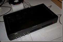
CRW_6825
Initial power up, the amp section seems to be okay (at least it doesn’t have any serious offset that might blow up a speaker if I connected one up. Aux and Phono inputs seem to be okay as well, so I hooked up a test speaker.
The FM/AM tuner sections were stuck at 0.00 on the display and would only move by 1 step (50Khz on FM) and go back to 0.00 when I released the UP/DOWN buttons. So I disassembled the receiver to try and fix that.
CRW_6826
I managed to get a service manual off the internet, it had the complete schematics plus tuner alignment instructions. Google “NAD 7125 service manual”.
Tuner
Initially I thought maybe the main IC controlling the tuner section was wonky somehow, so I set out to measure some voltages.
IMG_1743
Voltage checks on the ‘G’ ribbon (that carries power to the tuner section all checked out good.
Voltage check on IC6 (TC9137P) was ok as well.
Wires to the LED display were also verified to be good.
Output of a 5V regulator (78M05) IC7 was also good.
I managed to get the tuner to somehow work when I cut 2 cable ties holding the LED wires together as well as remove the LED display bezel to see if there was anything wrong there.
I thought somehow maybe the paper washers holding the LED display bezel had become conductive and impeded correct operation, but I was really not confident I had fixed the problem.
I went ahead and programmed a few of my favorite radio stations into the channel buttons and powered it up every day to see if the issue would recur.
The fault re-appeared 3 days later, but the difference was this time it was not 0.00, but rather the station that I had programmed into channel 1.
This of course makes sense now, the tuner hadn’t been powered on for a pretty long time and had lost all it’s internal memory, so the stored frequency in every channel was 0.00Mhz and it was trying to switch itself to 1 all the time even when I was tuning it manually with the rocker. The pushbutton switch on channel 1 was basically conducting sufficiently to cause the main tuner IC to sense it as permanently depressed.
I sprayed a little Electron 22 into the switch and exercised it a couple of times and tuner function was restored.
IMG_1748
At this time I went ahead and tweaked the amplifier’s center voltages and idle current to 0.00V +/-30mV and 30mA. Before tweaking it was running a very low idle current (2mA), not sure if it drifted or someone was inside here previously with a ‘golden screwdriver’.
IMG_1747
There are 2 potentiometers per channel on the amp that control the offset (center) voltage and the idle current. To do this you’d have to 1st zero out the output as best as you can (without any signal input of course, I do it by shorting out the AUX jacks, turning volume down to minimum and switching the input to AUX).
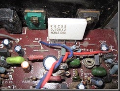
IMG_1749
The emitter resistors are what you’d need to measure to determine the idle current.
V=IR
I = 30mA and R = 0.1Ohms
V=(0.03)x(0.1)
V=3mV
So to get a 30mA idle current you’d need to adjust the pot till you get 3mV across 1 leg, each emitter resistor in this case is actually a combination of 2 in one package, with the center lead common (to the output). Check both sides after you’ve adjusted to make sure they are close.
After adjusting it in, leave the set for awhile and come back to re-confirm it’s still stable on both sides of the emitter resistor just in case it drifts.
I also spent some time dusting the interior, in fact the pictures taken above are after I’ve removed most of the dust.
IMG_1740
After listening to the receiver for abit I noticed yet another issue, the Stereo LED only lighted up very rarely and attaching a longer antenna plus shifting the unit outdoors (I was testing it in a semi electrically noisy environment, near PCs and stuff) didn’t help.
Measuring the MPX VCO output with my DMM that had a frequency counter option showed it running at 78kHz, which was out of limits, should be smack on 76Khz (+/- 10Hz).
IMG_1753
I don’t own a RF generator to test and align the tuner in accordance to the steps outlined in the service manual. So I used an alternative method to get it in.
I marked the VCO potentiometer in 3 places (it’s one of the those crappy wobbly ones that can shift around as you’re turning it, so it’s gonna be hard to get it exactly spot on if you only marked it in one spot) to enable me to return it to the original point if this adjustment didn’t help.
Then I tuned to a strong station mid-band (in this case I used 98.70FM).
Pot was then turned fully CCW (counter clockwise) and slowly turned CW to just where Stereo LED indicator came on, this is position A.
Pot was then turned fully CW and slowly turned CCW to just where the Stereo LED lit, position B is here.
IMG_1751
Finally I set the pot to between position A and B, measuring the VCO at this point yielded a stable 76Khz.
IMG_1742
Listening with a pair of headphones confirmed the tuner was in stereo (there was audio separation), switching to mono turns the Stereo LED off and results in no separation.
IMG_1744
I then tested other stations across the band (88-108Mhz) and found that they went into stereo reliably.
IMG_1755
After I was satisfied with the results I replaced the cover and touched up some paintwork on the front panel that was scratched. I still need to go out and get some replacement knobs though, but at this point I’m really happy with the results.

On a lighter note. Merry Xmas everyone!