Board in question is an Asus Blitz Formula.
Motherboard had a dead (corrupted) BIOS. Found an SPI header just below BIOS chip (SST25VF016). Time to use that to CPR the board back.
Board was flashed using Winflash, which didn't verify correctly after the write (and just frooze), post restart it won't boot up properly anymore. Winflash is bloody risky, I've used it a couple of times on my DFI NF4-Ultra-D without issues, but it seems like it doesn't like this board.
 |
| Map |
Using a multimeter I then probed and determined where each pin mapped to on the header. The left smaller sheet of paper maps out which pin of the LPT port maps to the pins on the header. You gotta supply a 3.3V source to the IC under programming using either a bunch of AA batteries, dropping 5V across diodes, a regulator etc. Whatever you do, make sure there's a good stable source of 3.3Vish juicing the IC.
 |
| Wired |
Next I wired up an LPT connector to it. The flashing app I'll be using is known as "SPIPGM2", what it does is that it bit bangs the LPT to simulate SPI. I didn't use any sort of buffer or 'protection' diodes or resistors on it, I figured it's gonna be on only for a short while and should be ok. You gotta have a LPT (Printer) port for this setup to work.
You can get SPIPGM2 from here
http://richard-burke.dyndns.org...SPIPGM2.ZIP
You're also gonna need CWSDPMI7 (Host process needed by SPIPGM)
http://homer.rice.edu...csdpmi7b.zip
Just copy the contents inside the BIN folder into the same folder where SPIPGM2 resides.
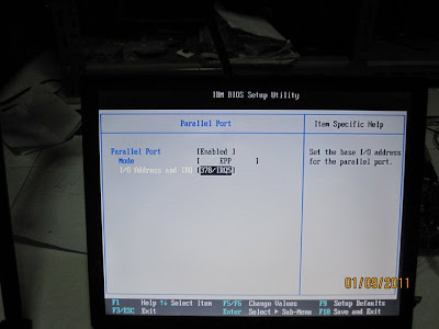 |
| LPT Address |
Before using that app, gotta make sure LPT is on address 378h in the BIOS. I've experimentally found EPP to be the most jitter/glitch free mode on this laptop. Yes I'm using a super old Pentium 3 IBM to do this (only thing I had around with an LPT port).
Your mileage may vary, give the different modes a try and then verify after each write to make sure the data on the SPI FLASH is corruption free.
 |
| NTFS For DOS |
I used a NTFS for DOS boot CD to let me read/write to my HDD that's NTFS partitioned (laptop runs WinXP). This allows me to place the necessary files (SPIPGM2 related) and then read and dump files onto the HDD. You can use anything as long as it let's you boot to DOS and can hold your dumps (Bootable thumbdrive, heck even a floppy disk).
 |
| Corrupted BIOS Read |
 |
| Prep |
Just for kicks I decided to dump the corrupted BIOS, to see how far Winflash got during programming before it b0rked.
After dumping I prep it for the write. SPIPGM2 /i Verifys that the system can recognize the correct type of SPI FLASH hooked up (25VF016).
SPIPGM2 /u and /e prepare the IC for writing.
 |
| Writing |
SPIPGM2 /s NEW.rom writes NEW.rom (which is the latest BIOS image downloaded from the Asus website) into FLASH. This process will take between 30-45mins on the 2MB flash (because of the bit-banging hackery used, if your processor is faster this will probably go faster). This is gonna take awhile. On my laptop it took something like 30mins to finish writing. While it's writing I'll take the time to show how I have the entire thing hooked up.
 |
| Hookup |
The hookup from motherboard to laptop, a little mess of 7 wires. 2 for GND and +3.3V, 5 for signals. Like I mentioned before, there are no buffers and current limiting resistors etc, so I wouldn't leave it hooked up forever (if somehow you decide that leaving it plugged in is a good idea).
 |
| 3.3V |
My 3.3V source was straight from an ATX PSU main connector. Shorting out the green (PwrON) to ground will make the PSU turn on, then probe around for a 3.3V source, it should be orange, although some PSUs might not have it in the same colour.
 |
| Write Done |
Yay! After 30mins it's finally done.
At this stage you may want to call it good, but I read the data back out so that I can verify it against the original later and ensure the write was 100% bit for bit good. Here's the read process.
 |
| Readback |
And here's me comparing it using HexCMP. Load both hexes up and then this will tell you instantly if there's a difference, as you can see, no problems here at all. 0 bit differences.
 |
| Compare |
The initial dump (corrupted BIOS), shows the 1st 2 bytes as 01 (which is not even correct), and then a blank chip after that, Winflash must've erased the chip right, but couldn't write properly. Lame.
Next would be to unhook everything and boot up the board. Glad to say that the board now works fine. xD


THX for the description helped me restore my (Blitz Formula board)
ReplyDeleteGlad I was able to help.
ReplyDeleteHello now it's my turn to sadly see how my Blitz Formula dies after an unsuccessful winflash...
ReplyDeleteI've just discover your blog entry and I would like to try your method, but I cannot see how you wired the LPT connector, neither on the connector nor in the mobo.
What I need is to see which LPT pins are connected and where in SST25VF016 chip. The pictures aren't very clear to me.
Furthermore, the link http://richard-burke.dyndns.org/wordpress/wp-content/uploads/2009/05/SPIPGM2.ZIP si dead.
Could you please help me?
Thanks in advance!
Angel
Sure, I found a blog post which is newer and better updated.
Deletehttp://wildbagger.com/wordpress/2009/02/programming-an-asus-p5b-bios/
He has pinouts and all properly drawn up> I just used a pencil to let me see how it's hooked up. Probably doesn't make sense to anyone else.
I have to commend you on your article! I had just about given up on my HP N54L Microserver that I incorrectly flashed with a custom firmware. The Boot Block was erased and I had nothing to start the recovery! Luckily my trusty Pentium 2 Compaq Armada 1750 came to the rescue with its built in LPT port! With nothing in between other than some logic probes and a 3.3v PSU, I managed to interrogate the Flash Rom and got a response!
ReplyDeleteI had to make sure I disabled that WP bit and enabled the W bit, as the first flash failed completely, and it doesn't tell you this!
Luckily, second time round I managed to flash the ROM successfully and got a BOOT to BIOS!
Although the HEX compare wasn't identical on mine!
2mb SST25VF016B 75-41-B2A - Flashed!
That's really neat,I'm glad this post helped you out. Did you reflash the ROM after you got the machine to boot properly?
Delete