Thursday, October 13, 2011

Success finally, after smacking my head against python for awhile.

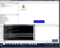
As above, thanks to FIzzisist for hammering out the new code. Programming now seems to work 100%, about 60+kb/s taking just over a min to program the FPGA, that’s plenty fast enough I’d say.

Pre-processing does take up a fair amount of CPU power though. Maybe later the processed stuff can be cached to a file or something.

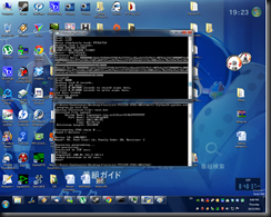
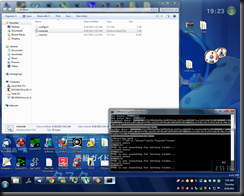
Anyways here’s a screen capture of the FPGA being successfully programmed and then the miner working (50Mhash/s code running, still haven’t got a heatsink for this yet).

Success

Apologies for the messy desktop… xD

Sunday, October 9, 2011

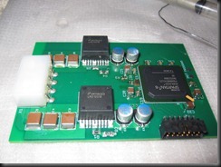
Finally populated everything.


Here’s a board fully populated. OSP really does suck if you plan to keep the boards around a while before populating them. I had to use a fair bit more flux then usual to get stuff to flow, and some areas were starting to oxidize already.

IMG_4949

I’m now putting desiccant packs inside the bag that contains the unpopulated boards, hoping that’ll prolong the OSP life and plan to put everything on at once instead of step by step with a wash in-between.

Side note: the fully populated board does work properly, still need to sort out the software side of things though. Watch this space for more details.

Saturday, October 1, 2011

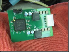
Got the board assembled

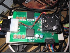
As per title. Received the parts from Digikey. Soldered them on and time to test.

IMG_1089

Puny little heatsink is for running test code, it probably won’t hold for anything serious (75Mhash/s and above)

Saturday, September 24, 2011

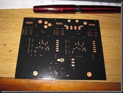
Boards are in!

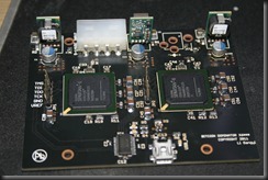
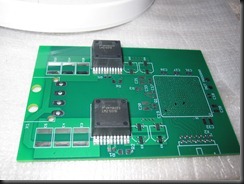
Here’s a couple of pics of the board, I’ve gone with an OSP finish instead of HASL, probably gonna be better for BGA soldering, but @ a cost of shelf-life. On well, can’t have everything. On the plus side, with some lead-free solder I’ll be RoHS compliant.

IMG_1083IMG_1084

Parts should arrive sometime next week. Looking forward to populating and testing this baby out.

Rev02 In the works.

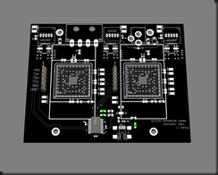
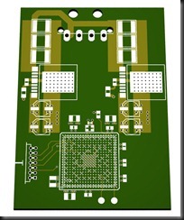
Shall let the pictures do the talking, working on getting USB functionality right on the board (no need for the platform cable), as well as a better front end this time round.

Here’s a render of the board.

FPGA

https://bitcointalk.org/index.php?topic=40058.0

Thursday, August 18, 2011

Here’s where it’s at now

Test
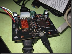
100Mhash/s on the test board at this point, I’ve made a few improvements to the board to get it reach this point. Namely a small heatsink+fan combo and some rubber feet so it doesn’t short on anything on my table. Below are a couple of pictures.
IMG_1077IMG_1078IMG_1079
If you (the reader) hasn’t figured out what this is for yet, it’s a bitcoin mining board based on a Spartan-6 LX150 FPGA, at current code, it does 100Mhash/s max, this is estimated to hit 150-200Mhash with improved coding and routing techniques. Me and 2 other guys working together on this project, are aiming to bring this low power, high performance board out as soon as possible, more still to come.

Edit: Alright here's where to buy one, I've only a couple left at the moment.
https://bitcointalk.org/index.php?topic=37904.0

And it works! Sorta…

Not anywhere close to pushing the max limit of the Spartan-6 FPGAs, but here it is, pushing out some real data.

Testing

It’s now 6am here, I need sleep.

I need to epoxy on some kinda heatsink to avoid frying my shiny new toy, as well as take some power measurements after I’ve stuck on faster running code. Should be cool.

More Testing. Chipscope is quite user-unfriendly.

Still getting used to Xilinx’s ISE. Inching forward a step at a time.

Testing

More updates, assembled board and testing in progress

As above, pictures below, those 0402 decoupling capacitors were kinda hard to get in place. A good magnifying glass really speeds things up.

IMG_1065

I assembled the LMZ power modules 1st, they have a huge thermal pad on the back that need serious heat to solder them down.

IMG_1066

Here’s the rest of the power supply section tested. Then I metered the output voltages, all within design limitations, before I proceeded (1.2v and 2.5v, measured was 1.18v and 2.48v).

IMG_1068

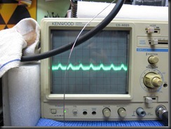
Some noise figures, scope was at 0.2mV/div with an X10 probe, 0% load, I need to retest this again at full load and with a better scope, current scope has a bandwidth limit of 20Mhz, which might not be showing everything.

IMG_1071

Then I assembled the rest of the stuff, including the Spartan-6 FPGA, I left some of the capacitors around the sides unassembled so I can visually inspect the BGA soldering quality (didn’t take a picture though).

IMG_1072

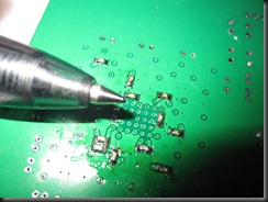
Next I tackled the underside, which has some 0402 decoupling capacitors. These were insanely hard to do naked eyed.

IMG_1073

Here’s a closeup comparison with a 0.5mm ball point pen tip.

IMG_1075

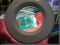
This is how I did it by hand (mostly), a good magnifier and strong light helps a lot, you don’t want weird shadows obscuring your view.

IMG_1074

A shot of the completed board through the magnifier. It looks good doesn’t it?

IMG_1076

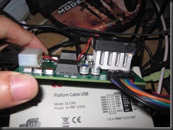
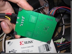
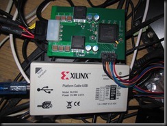
Here it’s connected to my cheapie Ebay chinese Xilinx platform cable clone, resting on my messy as hell table.

Wednesday, August 17, 2011

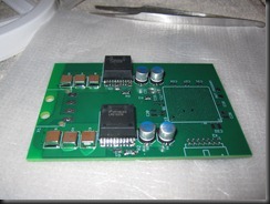
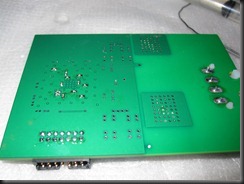
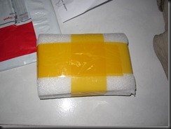
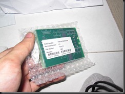
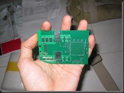
PCBs are here.

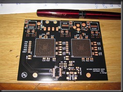
I shall let the pictures do the talking.

IMG_1060IMG_1061IMG_1063IMG_1064

PCB cart packed the boards relatively well, they were vacuum sealed with some desiccant inside, the only improvement they could’ve done was to include some kinda moisture indicator.

Preliminary visual inspection and electrical testing has found the board good. I spec’d a 1.6mm PCB, that’s just feels so rigid now I look at it.

The only complaint I have with the current board is due to the HASL finish I employed, the BGA pads are not very flat (or co-planar is the word I think). Nothing some flux and a little solder wick can’t fix. 

Will update again later once I get parts onto it.

Sunday, August 14, 2011

What am I up to 2.


Finally completed laying out and ordering part for my upcoming project. I’ll release more details about what it is later, should be exciting.

I had my PCBs made by www.pcbcart.com, my current design uses a 4 layer board, so it’s impossible for me to fab them at home. Short of some communication issues, I think they are fairly good, their lead times are (at your choice) 15 or 18 days (that includes ship time to you) and the prices are pretty reasonable (my board was about 80x60mm and it costs about USD$50 for each). There’s a 1 time tooling cost to generate the artwork (they accept EAGLE files and an operator will put out gerber files for you) and create the stencils+whatnot.

Although I can’t say their command of English was perfect (I had some trouble conveying my requirements across), but eventually I got them sorted. Their email response is fast and if they encounter a problem they’ll message you straight away for a confirmation instead of producing a bad board.

Electrical testing is also provided free as well, which is a good bonus, not cool if your board arrives with an inter-layer short.

As for the parts, well I ordered this time from Digikey, www.digikey.com, instead of my usual RS-components (I use them cause they provide next day delivery, however this time they didn’t have quite a fair bit of the parts I was looking for).

From the ground up my design was based on whatever Digikey had in stock, no point trying to put in a component that’s not easily available. They also do shipping free if your order is over like USD$100 (Might not be the actual figure, gotta check again). Shipping was fast as well, parts actually came before the board.

I’ve yet to receive the boards, so I can’t comment on PCBcart’s quality, but from what I’ve heard/read they are supposed to be not bad. Will update again. Until then….

Sunday, July 31, 2011

What am I up to?

Just a sneak peek at what I’m up to lately. Can’t reveal too much information just yet. Will do so in a later update.

FPGA

Monday, July 18, 2011

National’s New LMZ simple switcher module series.

Currently developing a power supply solution for the Xilinx Spartan 6 LX150 FPGA, and I stumbled across this cool modules from National.

They’re available in 1A-10A capabilities, if 10A is not enough, there are modules out there that can current share, for up to a max of 60A output.

The modules themselves come with an intergrated FET and inductor, meaning you don’t have to make a choice, don’t have to worry about best layout on your board, and it will magically just work.

Very low external parts count, you just need 2 resistors to set the voltage and then a bunch of capacitors and away you go.

Prototype friendly package, the module is housed in what looks like a D2Pak layout (except with a couple more pins), enabling good thermal performance and ease of solderability (compared to say QFN).

Low EFI/EMI, the inductor and FET are shielded inside the module, meaning you wouldn’t need to worry about component placement on the PCB.

There are a whole other bunch of benefits, the only cons being a slightly higher initial cost and no way to tweak say the FET or inductor to a ‘better’ part because they are built in.

Web-bench enabled, this web based app will spit out the schematic, BOM and let you simulate electrical and thermal performance for your spedified inputs and requirements, makes gauging what kinda performance you’ll get in your final design easy.

The list goes on and on and on. Check them out on.

http://www.national.com/en/power/simple_switcher/power_modules/index.html

Anyways here’s my PSU design at the moment.

FPGA PSU brd

Tuesday, July 12, 2011

Speedtouch ST536v6 Repair

Came home one day to find my modem’s lights were all out. Abit of probing with a multimeter found the adapter to be dead. Thinking that it was just the adapter, I dug out a replacement and put it on. Things went downhill further when something on the board released it’s magic smoke and the modem wouldn’t sync properly (everything was there but the ADSL link light wouldn’t come on steady).

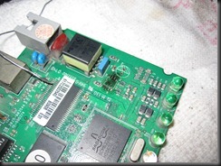
Visual inspection near the vicinity of the smell, I found the receiving buffer, an STmicro TS613I part visibly burnt. Oh well… I don’t really like throwing out stuff, even though I’ve got a couple more spare modems on hand I think I’ll fix this (it’s been working very well for the past 4-5yrs actually).
A search online on my favorite parts suppliers (RS/Farnell etc.) didn’t net me any results, they didn’t carry the specific part. Then I thought I’d try TI, they ship samples out fast and Burr Brown has some insane Opamps I’d like to try.

A search on TI’s keyword based system found me this.

http://focus.ti.com/docs/prod/folders/print/opa2613.html

OPA2613, it’s even listed as a TS613 replacement, aha! I thought it’d be a drop in replacement, but it looks like it’d take a slightly lower max voltage. The rest of the specs (noise, slew rate etc.) were looking better then the original part. I ordered a couple of samples and they shipped it out within 2hrs through FedEx International Priority with a tracking number.

3 days later I had the part in hand, I love the super fast shipping, thumbs up to them, and I proceeded to remove the old part, replace it, and then make modifications necessary to make it work reliably.

IMG_1033

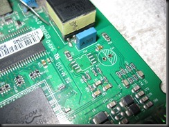
Here I’ve taken out the fried TS613, I think the part failed after prolonged use because the input voltage drifted over it’s max rating (the voltage source is fed from a LM7812 with a couple of external resistors to set it’s output voltage close to 14v, however one had drifted in value due to the heat or maybe it drifted because of the fried TS613? Wouldn't know for sure.) and I measured 14.5 (not a safe working voltage for sure, datasheet for the OPA posted a max rated working voltage of 12.6), I don’t know why they went with such a small margin for error, and it really seems like they were pushing the envelope (even the TS613 recommends it’s operating supply to be @ +/-6V, making it a total of 12V). I’m guessing they needed the extra voltage to make sure the output wasn’t clipped or something.

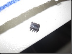
Here’s the fried TS613

IMG_1034

Prepped the board with some flux and wicked off the excess solder. I had to remove a capacitor off the board for some clearance around the part.

IMG_1035

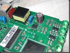
Here’s everything in, OPA2613 and capacitor.

IMG_1039

I modified the supply back to 12V (from 14) by removing the 2 external resistors and then tying shorting the GND of the 7812 to the board’s GND.

IMG_4945

It now works, I’ve yet to experience any sorta dropout in connection yet. Will update if it does die or something again.

Monday, July 11, 2011

Turn Aquarium Pump into Vacuum (Cheapie pickup tool)


I needed some way to suck small SMD parts up without having to buy a $$$ vacuum station. Already had a cheapie $2.50 pickup tool (with a rubber bladder thingy), but that wasn’t working all that well especially if the component doesn’t have a completely flat surface. The pen will eventually loose vacuum and cause the part to drop, and you don’t want it to drop when you’re not prepared, it’s almost impossible to find it later.

A good friend passed me an aquarium pump to see if it’ll convert over (thing costs less then $5 new). Here it is intact.

IMG_1005

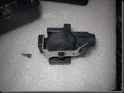
Taking it apart reveals a rubber bellow and some kinda diaphram valve system. To make it suck instead of blow you’d just have to rotate the valve around so the sucking side now goes to the port.

IMG_1006

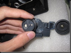
Here’s the diaphragm/reed valve system.

IMG_1007

I ended up having to cut away a couple of positioning pins, because the new location doesn’t have holes for them to go into, and then using a drop of glue to hold everything square while I tightened the center screw.

It works, I can now suck up parts and not worry about them dropping randomly.

Sunday, June 26, 2011

Upgrading My Raid Array and running into problems.


Recently upgraded my RAID0 array from 4x500GBs to 2x2TBs for more capacity.

Then I ran into problems.

MBR partition tables won't let you have an array over 2TB large. GPT does support >2TB, but you need an UEFI bios to be able to boot from it.

I'm using an aging Evga 680i that sure as hell won't see UEFI anytime.


Guess I'll stick my OS on a smaller HDD and run apps and everything off the array in GPT. zZz

Friday, June 24, 2011

Notebook Graphics Card Repair


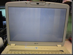
Had an Acer from my aunt come in for repair the other day, it had bleeding graphics issues and couldn’t boot into windows (or at least you couldn’t see it go in anyways). Here’s what it looks like just after power up.

IMG_1000

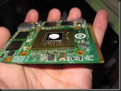
I disassembled the whole laptop down so I could get the graphics card out (it was in some sorta MXM slot in card).

IMG_1001

Card is an 8600M, a lot of these are notorious for failing during service (due to bad underfill material). Didn’t have anything else to lose, so I just fluxed the BGA and then put it on the rework station.

After rework.

IMG_1002

Usually I clean the residue flux by using a Qtip and then some IPA. If the board is small enough (like in this case) I chuck it into an ultrasonic cleaner to get everything out, if the board’s too big I just leave as is (and try to use as little flux as possible), or if it’s real bad I try and squirt some solvent in between the BGA and the PCB.

Glad to say that after just reflowing the solder joints under the GPU, the gfx card started working normally, how long will it last I wouldn’t know, will post another update if it ever dies again. Till then… xD

Thursday, May 19, 2011

Pioneer DV-500 SMPSU Repair

Pioneer DV-500 that wasn’t powering up arrived on my bench one morning. Managed to diagnose it down to the SMPSU being dead. Forgot that I’d left my trusty DMM at my workplace, so I hauled it over to the shop to get it fixed.

I found a slightly different model’s service manual floating online, but it utilised a close enough power supply that the schematic and board layout were almost a 1:1.

Here’s a shot of the power supply. Those are some good quality capacitors they’ve put on there.
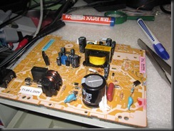
IMG_0962

The standby voltages were ultra low (1v for a usually 3.3v supply), and was oscillating. In the service manual there was a block diagram, some troubleshooting flowcharts as well as the full schematic.
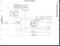
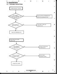
Pioneer DV-300-K (RRV3584)_Page_22

Pioneer DV-300-K (RRV3584)_Page_23

I checked everything around the 3.3v supply and couldn’t find anything wrong, the main controller IC was getting the right amount of voltage from the bias winding (around 13V), was scratching my head for abit and then decided to test everything to see if something was shorted, causing the PSU to not come up.

Very quickly I managed to find a shorted secondary rectifying diode, it was on the 5v line, I desoldered it out of the circuit and confirmed it was a dead short, these things are known to fail.
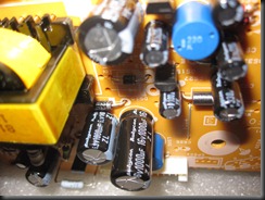
IMG_0965

I repowered the PSU, expecting it to come back online since regulation was done on the 3.3v rail, but no, the bugger still wouldn’t come on.

This was when I decided to give up on the block diagram (it wasn’t showing everything) and use the schematic. Finally it became clear that there was protection on the PSU that prevents the outputs from coming live if any rails had low or missing voltages.
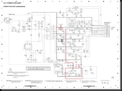
Pioneer DV-300-K (RRV3584)_Page_60

PNP transistor Q506 prevents the power supply from fully coming on if the voltage at the base is lower then the emitter, the emitter’s voltage in this case is regulated by zener diode D523 to around 3.6v, so anything lower then about 3.0v will cause it to conduct and through the optocoupler, shutdown the supply.

In this case the base is indeed lower then 3v, about 0v in fact, due to the missing 5v rail. Once I figured this out, I tried lifting one pin of D522, which ‘feeds’ (can’t really say feed here, it’s more like leak), to the base of Q506.
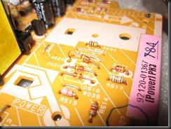
IMG_0963

That finally made the power supply start up, and the other rails measured good, confirming that the shorted 5v diode was the only bad component. I couldn’t located an exact replacement, so I dug one out of an old PC PSU (which is a lot beefier then it really needs to be on this PSU).
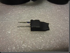
IMG_0967

I put some heatshrink on the metal tab of the diode, to prevent it from shorting against anything on the board.
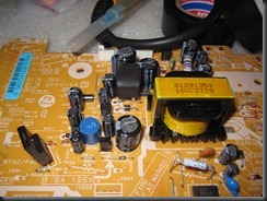
IMG_0968

Here it is in it’s new home.

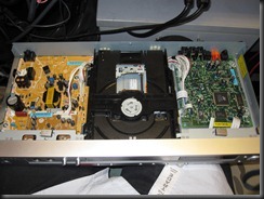
Pieced the entire DVD player back together.
IMG_0969

The DVD player uses a Mediatek 1389 SoC to do all the decoding, pretty famous for it’s DVD-VIDEO, DVD-AUDIO, Super Audio CD, DivX, WMA, WMV, JPG, MP3, and MPEG4, as well as its high-quality Pal-to-NTSC and NTSC-to-Pal conversions. Ah well, blu-ray is all the rage nowadays.

Anyways it works properly now, –1 DVD player in the landfill.
IMG_0970

Xbox 360 Xclamp replacement.

The Xclamp is Microsoft’s weird heatsink retention mechanism that puts undue stress on the Xbox’s motherboard, leading to warpage and then finally the solder under the GPU/CPU gives way and then you get an RROD. I’m replacing that with a couple of screws and washers to prevent board warp.

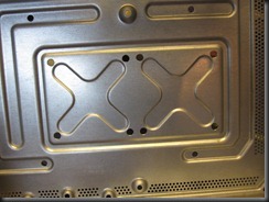
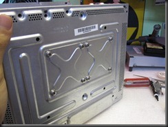
1st you’d need to enlarge the stock screw holes on the chassis to 5mm dia to get the new screws to fit.

IMG_0974

Then you’d need to get hardware to mount the whole thing on. You’re gonna need a couple of M5x0.8x16mm screws and 1mm thick washers to get the dimensions right.

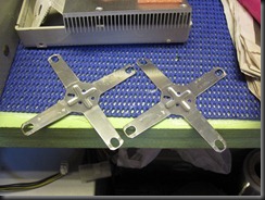
After getting all the hardware, take off the stock retention studs on the bottom of the heatsinks, and also cut away and flatten the stock Xclamps.

IMG_0973

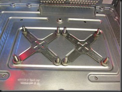
Once done, start putting in the hardware.

IMG_0976

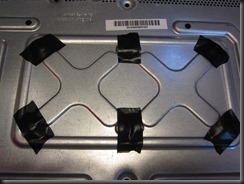
I use some tape to temporary prevent the screws from falling out when I tip the chassis over.

IMG_0978

The flattenned Xclamps go on, and then enough washers to make up 3mm height.

IMG_0979

A piece of 4mm foam underneath provides support around the CPU and GPU area.

IMG_0981

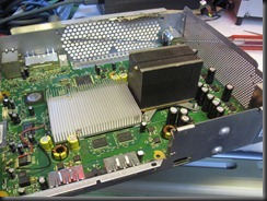
Put in the heatsinks and lay the Xbox on it’s side, then tighten the fasterners, in a cross pattern to exert even pressure.

IMG_0980

Once done, put together the Xbox as per normal.
Credits to http://xbox-experts.com/tutorial/team-hybrids-ultimate-xclamp-fix-released/ for giving me this idea in the 1st place.